ADC upgrade
for G3RUH 400bps Phase3 PSK Data Demodulator mkII
Japanese
What's the ADC upgrade ?
What's the 400bps PSK Data Demodulator ?
Installation, adjustment and first capturing FEC coded telemetry with P3T
 Parts required for the upgrade
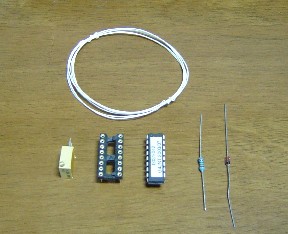
Parts included in the upgrade kit provided from James Miller, G3RUH are shown.
Front left, 10k ohm trimpot, 16pins DIL IC socket, ADC chip, 1k ohm registor, zener diode, and the above is wire for 'hook up'. The instruction leaflet is included in the kit.
Addtionally you need to prepare a blob of epoxy adhesive to mount the trimpot onto the PCB.
 Mounting the trimpot
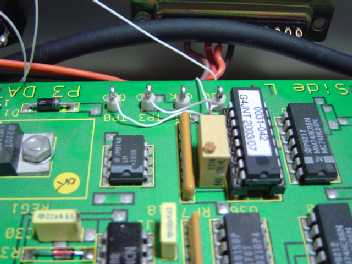
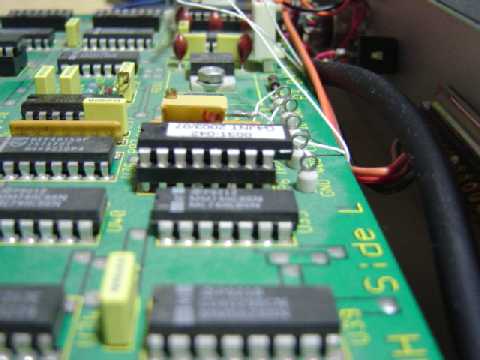
In my case, I placed the trimpot next to the ADC chip with adjustment knob faces upward.
 Tricky way ?
Originally the ADC chip has 18pins DIL. Snipped pin 9 and 10 to insert the chip into 16pins DIL sokcet. Actually when I got the kit from James, the chip has snipped already.
When you finish the installation,adjustment follows. See the leaflet. Begin with the "Method 1".
 Method 3, final step of adjustment
P3T will be great helpful to do the adjustment Method 3. In other word, there's no way to do but for the newer P3T. Follow this instruction instead the original leaflet because too principle instruction provided for Method 3.
1. At first you need to obtain the newer P3T. Later than v2.0. If your P3T is obsolate, you can't take "ADC" as modem type. The latest P3T is here
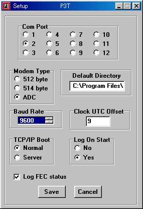
2. Change the P3T setup to enable the ADC service thru the RS-232C. Go thru "Menu" to "Setup" , then you see the this windows. Take "ADC" as modem type, and "9600" as "baud Rate".
 Method 3 (continued)
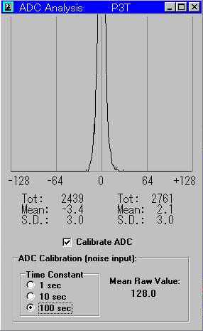
3. Input radio noise to the demodulator. Again Go thru "Menu" to "ADC Display".
4. Check in the box of the "Calibrate ADC", then you see this window. First take "1 sec" as Time Constant, then watch the "Mean Raw Value". Turn the trimpot CAREFULLY a little by little to lie the value within the range of 128 +/- 0.25. Once finished, change the time constant longer, do that to confirm the value.
 front panel
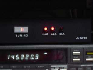
While you are receiving the FEC coded telemetry block, the LED of CARand CLKare ON, BLKkeeps off. But about 13seconds later, you will see...
 Project completed.
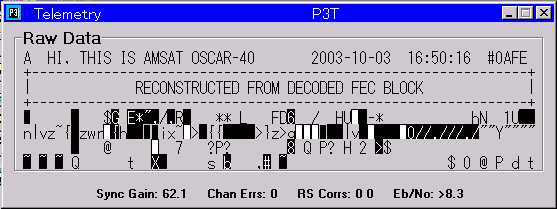
You will see the decoded FEC telemetry block in the "Telemetry Window" of P3T. Your project now completed.
400bps FEC telemetry will be used also on the next Phase 3 satellite, and FEC telemetry must be used on the Phase 5-A satellite to Mars. I don't know the 400bps or lower, but the FEC is sure.
ADC histgrams
other examples
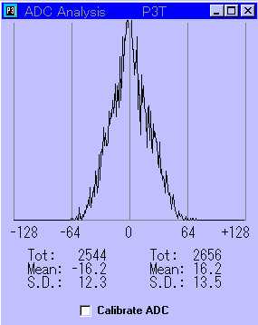
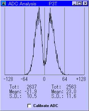
_______________(L) Eb/N0 approx 1dB ____________________(R) Eb/N0 approx 5dB

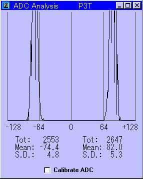
_______________(L) Eb/N0 approx 8dB _____________(R) Eb/N0 approx 8 dB with better G/T system
links
Top of my web pages: [English] [Japanese]
Email to: jj1wtk at jamsat.or.jp

created: Oct 11, 2003
last update: Oct 15, 2003